Some more superstructure in Issue 14, plus a little on the Sporting Life of HMS Hood, an interest to me, as on page 46 there is a great picture of the trophies that were won during the Rio trip of 1922. The footage I've linked on this blog that show Arthur standing in front of these trophies.
Back to the build, a little more work to do here rather than just cut from ply and glue, so take your time and dry fit..as always!
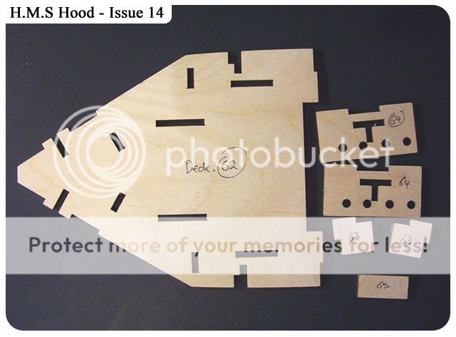
All part marked and cut from ply, give them a little sand.
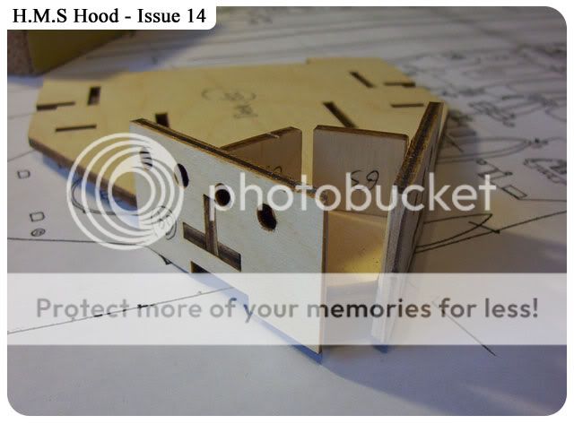
Once again I wanted to see how this model is comparing to the plans from John Roberts book, so far I'd say they are pretty good. Here part of the Forecastle deck is laid over the plans.
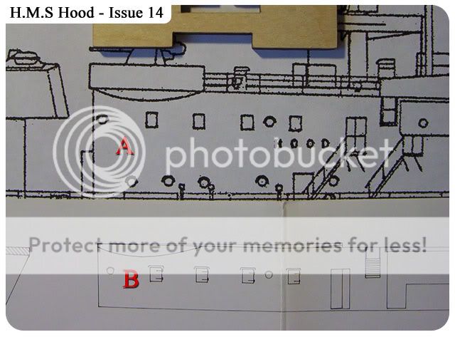
The 2 wall pieces (part 64) is laid against the plans, as you can see the pre cut port holes are not in line with the plans, I'm guess Hachette are giving us the option of having these windows open or closed??? I may just increase the 2 right hand holes to match a little more against the plans...I'm undecided yet.
Carrying on from the above picture I've laid 'Profile Morskie' plans (B) up against Roberts plans (A) and they seem to be a better match..BUT 'profile Morskie' is NOT the best plans to follow, I'm just double checking what I have.
Dry fitting all part's except wall piece 65.
I've marked (very roughly) the position of the 2 right hand port holes plus the Quarterdeck's port holes and door, just out of interest.
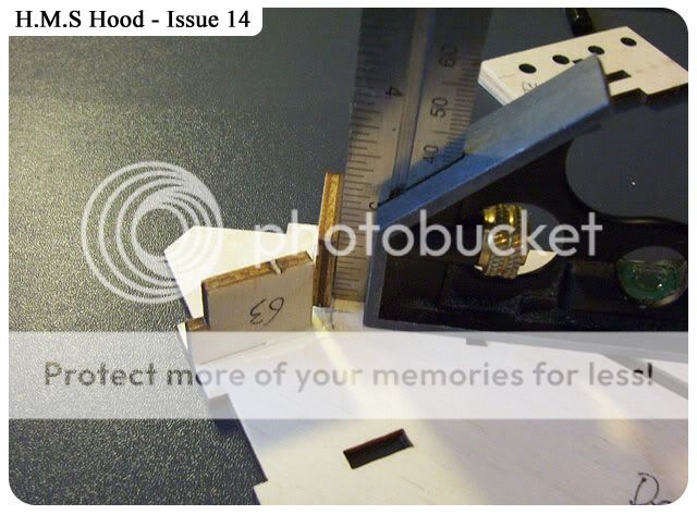
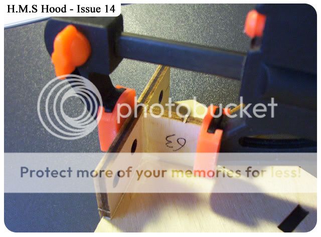
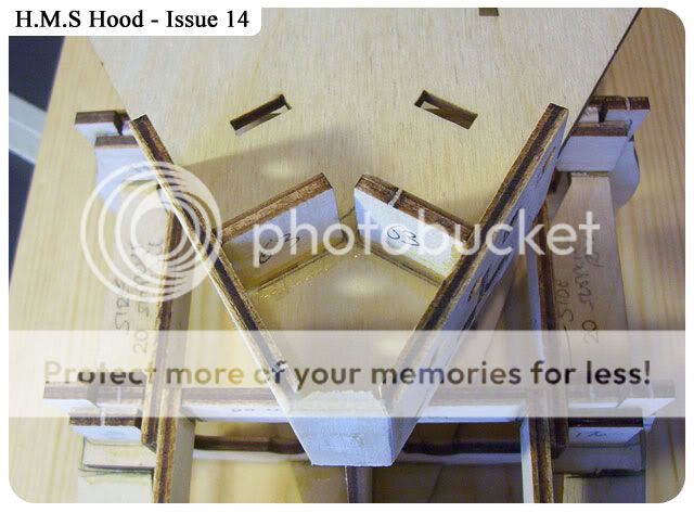
Starting to glue parts 63 to deck part 62, use a set square to keep parts 63 upright and square.
Once they have dried enough I'll now add the wall piece 64, using a small clamp to butt that piece hard up against part 63, do this for both sides.
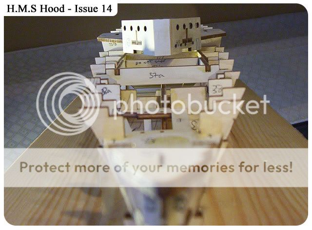
Part 65 glued into position, remember there will be some Photo-etch material covering this area (hopefully) so make this as flat as you can and as square as you can, the inside will not be seen.
Next Issue (15) looks to be more parts for the section
It's starting to look like the 'Hood' now.
Just for fun I've drawn very roughly the cabins that make up this part of the Forecastle.
56- Admiral's Day Cabin, 55- Admiral's Dinning Room, 54 - Admiral's Sleeping Cabin,
52 - Admiral's Pantry, 51 - Admiral's Bathroom, 53 - Admiral's Lobby, 50 - Secretary's Cabin,
49 - Chief of Staff's Day Cabin, 48 - Chief of Staff's Sleeping Cabin, 47 - Chief of Staff's Bathroom,
9 - Engine Room Vent, 46 - Secretary's Cabin, 45 - Secretary's Clerk's Office,
44 - Engineer Commander's Cabin, 43 - Surgeon Commander's Cabin, 57 - Commander's Cabin,
58 - Gunnery Officer's Cabin, 59 - Gunnery Ready Use store, 60 - Billiard Room,
61 - Paymasters Commander's Cabin, 62 - Squadron Commanders Cabin, 63 - Commissioned Officers WCs & Urinals, 64 - Subordinate Officer's WCs & Urinals.


hi. excellent job your doing, i must be doing mine right, looks very much the same except for the plans. keep up the excellent work look forward to your build dairy to reassure myself .thanks dave
ReplyDeleteHi Dave, blimey mate, you posted quick, I've only just finished uploading..ha, thanks:)
ReplyDeleteCheers Colin
You laid part 64 on the plans and the portholes did not line up, but as this piece is at an angle the perspective will be different on the plan. Therefore will the portholes actually be correct?
ReplyDeleteI have another plan I bought some months ago on fleabay, the plan is a larger 1.192 but it seems to of been photocopied and scaled down as it match almost our 1.200, on the area concerned, the port holes, seem to match better than the Roberts plans. On making the 1.192 model you would use these to mark and cut your side walls and port holes according to the plan, hence no angle would be taken into consideration, I would also say the Roberts plan would be the same, so with that in mind I'm pretty sure (99%) that the portholes on the part supplied is a little off the position shown on Roberts plan (which is said to be pretty accurate),I wont be taking any action on adding or taking away until we are further into the build, just a little thing to watch out for..IMHO..ta Colin
ReplyDeleteHi
ReplyDeleteyou are comparing a angled wall to a piece you present parallel to the viewer so you'd expect the openings to be 'out'.
by laying the angled part against the plans is vary basic, there is no intention to compare the size to be accurate, but the port holes are in a different position when comparing on the plans..that Im 100% positive of.
ReplyDeleteQuote > "but the port holes are in a different position when comparing on the plans..that Im 100% positive of."
ReplyDeleteHi
I'm referring to the image (issue 14, pic 3). It looks like an angled wall on the side view of the plan is compared to the wooden part that is held parallel and found wanting.
Whereas this angled wall should be compared to the 'plan' view of the ship, not the 'side' view.
If you have a mind to, you could transfer the lines of the hatches down from the 'side' view to the 'plan' view on your sheet in light pencil.
Up to you. The model looks good, enjoying the build?