It's been a while again, I've still been working on the model but parts have taken time and I was not going to rush it, I think the hold up was trying to figure out a way to incorporate metal barrels, instead of jumping in and not thinking I took some time out and had a look around at how other modellers have approached the subject.
I've also got myself a new camera (Fuji T200) which has given some excellent results, it's only a small compact but it does have some manual setting and as I workout what they do I can hopefully better my pictures and quality.
What about the live stream the other day at 2844metres down in the Denmark Straight, that was fascinating, for those not aware there is a expedition to recover HMS Hood's bell, located in the debris field of the stern area, the last footage I've see was the ROV come within 10cm of the bell with superstructure overhanging, unfortunately they had to abandon the dive due to bad weather, I hear it starts again on 28th.
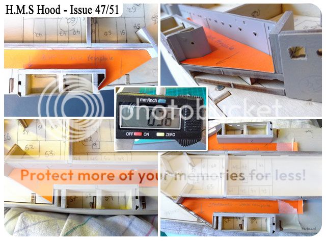
To start things off I wanted to cover myself with a small card template of the area that will hopefully soon sit the decking, I was holding off adding the quarterdeck sides due to this problem - lack of room to work. So after a few attempts to get the correct shape I now have a template both Starboard and Port that I can use to help cut/trim if needed the decking to be added. The centre image shows the thickness of the card I used, just in case anyone wants to know.

(top left) I've taken some time to carefully check to make sure this part was flat and even before gluing, again take your time to get everything ready to hold it in place as the glue sets. (top right) adding the small angle piece this picture shows all the levels of planking so far, Ive got no idea how they (Hatchette) will work this, but what I do know is that the piece needs to be fitted at some point..might as well be now. (bottom left) A small scrap (good quality) piece of wood laid across the part glued and the previously built section to make sure they are even at the top, another scrap of wood held in place with a pin to push the lower part in while it dries. (bottom right) Before the glue dries carefully take the whole deck section of and check the small piece has glued properly.

(top left) Finishing off the other side of the model, again scrap wood to prevent movement. (top right) Now starting to add the brass P/E material, after spending time to be 100% sure I know where this part lies, nothing will be covering this part up so I have to get it 100% spot on. (bottom left) The other side panel (with Hood's name on it) is positioned and checked before gluing, just as a point of interest I decided to add some of the card underneath this brass section to lift it a little, why? I felt once the decking comes the door will be far too close to the printed deck..my personal choice. (bottom right) Again I decided as I was working on these brass panels I wanted to finish this area now rather than wait to be told too, the brass has been available for some time and it is obvious where it goes, a little trimming and it sit nice a snug, again my choice to do this now.

(top left) With this brass end plate I noticed the wood it sits on was not completely flat, so I added some tape just to lift it outwards. (top right) A side on shot and you can see what I mean. (bottom left) Now these are the jobs a like doing the most on models, adding things that are not on the 'out of the box' model. On most if not all the models I've seen (except this one) in the location shown by the red circle there is from 1920 up till 1940 (please correct me if I'm wrong) a vent, have a look around and you'll see what I mean. But after one of her later refits this was covered, I noticed it more on the colour footage, after doing some research I discovered it was covered what I though was a simple flat piece, but most of the pictures I've seen there is a shadow, on looking closer I have interpreted it as the picture shows. Nothing is glued yet but I am more than happy with it. Notice one end is open and facing towards the stern. (bottom right) A top view showing what I though was just a flat piece added here.

(top left) This picture taken in September 1940 shows circled that vent cover. (top right) The colour footage again shows the cover, notice the shadow. (bottom left) Taken in March 1941, a big thanks to the
Hood Association for allowing me to use this picture. (bottom right) My attempt at this cover, again not glued in position. I have searched the copyright owners for some of these pictures but unable to find anything, please contact me if you are the copyright owner and I will amend them.
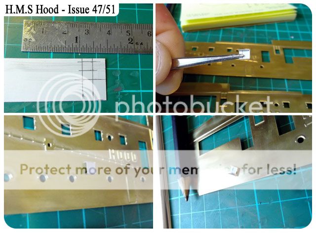
(top right) So this is how I did the covers, using some litho plate I marked 2 square's. (top right) with some care cut these out with the addition of two side and a back, using the P/E bending pliers shape them. (bottom left) After shaped I decided to add a small scrap of wood inside it so the glue has something to stick to on the brass panel. (bottom right) As you can see it's small...they are slippery little bugger's.
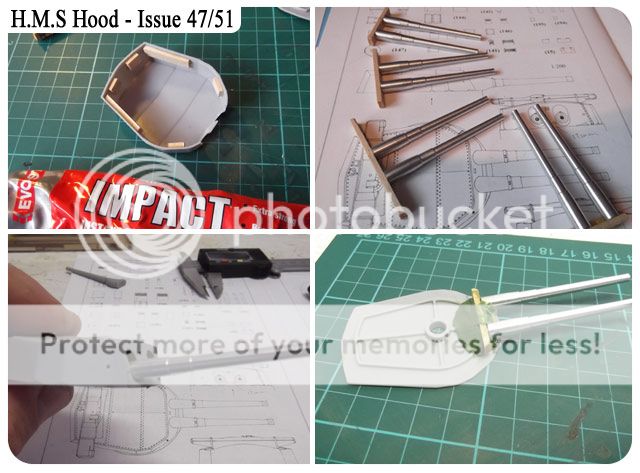
(top left) Now on the the 'big guns', a surprise to some that we have these turrets so early but it does give us a break from planking the hull. A top and a bottom plastic turret with some nice P/E. (top right) Laying the turret on top of the plans, seems about right too me. (bottom left) Some time ago I got hold of some metal barrels, they cost a few quid but let's face who thought a part-works series would supply anything other than plastic? I think a wise investment. (bottom right) A nice load of plastic addition to be getting on with.
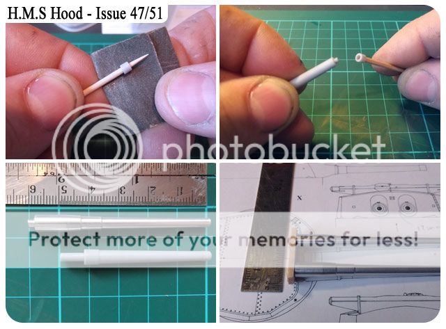
(top right) I wanted to see how the 'plastic barrels' went together to give me a comparison of size against the metal ones. using a cocktails stick sand the muzzle. (top right) With the same cocktail stick offer the muzzle up to the main barrel. (bottom left) And here we go..plastic vs metal...no contest for me. (bottom right) Now this part took me the longest, to come up with an idea not only to hold both barrels the correct distance apart but how to attach them to the main turret...I used a small drill bit and made to holes in a scrap piece of wood and stuck the barrels in, they stayed in and seemed quite tight without glue. After comparing both the McKay plans and the Morskie plans I managed to drill the holes in another piece of wood to give me the correct distance apart.

(top left) Now working on how to add these barrels to the turret, or in this case the base of the turret, After taking of some plastic I found this could give me some working space to build up and lay the wood & barrels to give me a good angle. (top right) I simply played around with various thickness of wood to find something that was right, no measuring was done in the making of this modification, just trial and error. (bottom left) My barrels and its wood housing laid over the Morskie plans, they were in fact identical to the McKay plans, so for ease I used Morskie. (bottom right) Now by laying and pressing down the barrels rise to the angle shown in the picture, to say i was happy was an understatement..BUT..after leaving it for a while and coming back i felt the barrels were to low down on the base, they needed to go up a little more.
(top left) Again I didn't like the very small lip that was on the main turret top that would sit the base, too small and once glued if your working on it my heavy hands would push it through, so I added some scrap wood all the way around, this give the base something more to adhere to. (top right) All metal barrels secured in wood with the correct distance between. (bottom left) By adding the turret top (dry fitted) you can see what I mean about being too low, not much but too low. (bottom right) This was my first attempt and holding the barrels at the correct angle..Green Stuff, I'm sure most of you have heard of this, you mix up yellow and blue to make green, the more blue the harder it goes, the more yellow the more time you have to work with it and it is also softer to work with. I used 50/50 here.
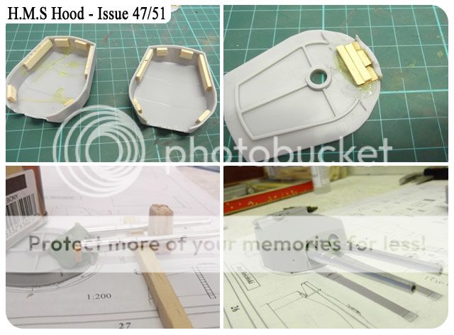
(top left) Both turret tops with wood surrounds completed. (top right) Another go at raising the wood by adding a small section in the middle seemed to have done the trick. (bottom left) Barrels laid in top of the wood and 'GS' (Green Stuff) moulded around with some wood to keep position. (bottom right) The finished turret, I think that's about right to my eyes, the range finder is added to the top un-glued at this stage, the more I keep off the turret while I work on these barrels the better, leave the 'GS' for 24 hours to completely cure.
(top left) The range finders seem to match the plans ok. (top right) Once again some modifications, opening up the view finders here, I'm not going to attempt anything other than what you see, if I made a mess it's a big job to correct, so this will do, start with a small drill and progress to a bigger one.
(bottom left & right) After drilling the holes in the main turret I squared out the middle one ok, but the two on either side were a problem, so I drilled a hole bigger than I needed and made a 'plug' out of a cocktail stick and used some 'Milliput' to stuff in the hole and use the 'plug' to create the square's you see, leave it overnight and lightly sand to clean it up.
(top left) Back onto the barrels, everything is ready, both sets of barrels are cured with some generous amounts of 'GS' and turrets are ready. (top right) After gluing the turret base to top there was some touching up to do, the join needs some 'Milliput' (bottom left) And after filling a light sand. (bottom right) I checked the base and filled the small gaps, this wont really be seen but as I still had some 'Milliput' I used some.

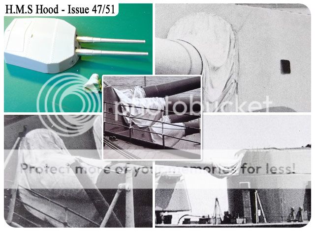
(top left) This is my first attempt and using 'GS' let alone creating a canvass blast bag on a large scale warship model...no pressure eh! I'm sure there are folk out there that can sculpt anything but for me I found this HARD to get the shape I wanted, I started with some 'GS around the barrels first and added the top and bottom bits. (top right) As it was drying after a few hours I went back and started to mould the canvas 'wrinkles', keeping the sculpting tool wet. At first I was happy..ish, In the back of my mind was there is too much 'GS' (bottom left) I decided to lay some thin paint to get rid of the green colour and see how it looked, ok! (bottom right) Onto the next one..Arghhhh!!! for some reason I couldn't match what I had on the first one, right so think about it...I walked away and had a beer. I started to sculpt the canvas creases on the second turret and noticed it looked better, a lot less 'GS' than the first, at a distance they both looked superb, but this is my ship and I wont be looking 'at a distance' I slept on it.
(top left) After 24hours I looked again and decided..nope, take 'em off, didnt like it, in fact what needs to happen is 2 things, first is wait until all 4 turrets are ready for blast bags so I can do them at the same time, and second use a lot less 'GS'
(top right, bottom left, bottom right & centre) With all the books I have I sat and flicked through them to find what I think are the best representation of Hood's blast bags, notice how there is in fact not a massive amount of canvas and the creases/wrinkles change depending at what angle the barrels are. So with this in mind I will wait until all 4 turrets and barrels are complete before going for it again, I think 'GS' works well, just that I need to practice a bit more.
(top left) a front shot of the completed 'Admirals quarters' looks good eh! (top right) I'm glad I did the template for the decking, if the decking needs trimming then I wont have to go anywhere near the P/E, just use the template. (bottom left) final shot of the Admirals quarters before more work begins with the doors and vents, oh don't forget we do have the window shutters. (bottom right) work still to do.


Brilliant as usual mate , im months behind but now have to weeks holidays , so will start 2nd planking & hopefully catch up a bit , thanks for all the tips & pics , Louis
ReplyDeleteThanks for the lesson, Im learning from this blog.
ReplyDeleteBuilder
Thanks for the comments.
ReplyDeleteHi Colin,
ReplyDeleteAnother great post as ever, up to your usual standard !
I have to say your metal barrels look splendid (I had read somewhere you had them up your sleeve) but to be honest I feel a bit like a “second class” citizen,
Like myself and others that are following your build we won’t have metal gun barrels so It feels that we’re kind of left behind ! LOL
I have limited myself to just one question you will be relieved to here :)
What is the type of adhesive do you recommend for the hoods plastic to plastic
parts ?
Kim (MOB)
Hi Kim, thanks for the comments, I use superglue at the moment, just a small amount, the less glue used the less to clean up.:)
DeleteJust got Issue 52 and guess what...3rd turret.
cheers
Colin
Thanks Colin,
ReplyDeleteHave you got enough barrels ?
Kim.
yes? 8 barrels.
DeleteHi Colin,
ReplyDeleteIf you have the time I wondered what is your take on this, I know by now that you are a stickler and have an eye for detail, so case in point for example issue 47 parts 201 and 200 called "frames" for the gun turret, I have looked at many images of this turret and can't find any evidence that they actually existed and what exactly was there function.
So then I had a brain wave (something I'm not accustomed to LOL) I remembered that a couple of years ago I purchased the first issue of "build the bissy" for 50p that came with a dvd, so I thought it would worth it just to watch it, I watched again today and it seems to have more meaning to me now, however still no evidence of these frames !
It's also a bit creepy because I had forgotten the discovery of the remains of the hood footage taken by the "R.O.V" which included the hoods bell and the laying of a memorial plaque.
I'm sure you must have seen it but I thought it was a coincidence given the attempt to raise the bell at the moment.
Cheers Kim.
Hi Kim, Cant say I know either Kim, but I have seen it on pictures of the real Hood (as opposed to models), I'm guessing it was a left over perhaps from the aircraft catapult of the late 20's, maybe?
DeleteOk Kim, I've done some searching and found this (direct from the Hood Association web site)
Delete"X" Gun House Platforms- These were not flat angular platforms in 1941. They were actually two identically sized frameworks (when viewed from above, they were made up of square segments with X cross beams in the centre of each square). Each "platform" consisted of three such squares. The only reason one appears smaller than the other is because of the changing shape of the turret beneath them. This causes a bit of an optical illusion. Click here to see an image of the frameworks
http://www.hmshood.com/hoodtoday/models/trumpeter/Foethturret.jpg
For those who still aren't convinced, here are two photos.
http://www.hmshood.com/hoodtoday/models/trumpeter/xplatforms.jpg
Still not convinced? Then here is yet another photo.
http://www.hmshood.com/hoodtoday/models/trumpeter/Xturretwidth.jpg
The latest photo to show the frameworks in place was taken in Spring 1941.
http://www.hmshood.com/hoodtoday/models/trumpeter/xturretmore.jpg
Needless to say, if anyone disagrees with this, they'll need to have spectacular documentation!
Vents on "B" and "X" Gun Houses- These gun houses each had a pair of slim vents that were attached to their rear bulkheads. These can be replicated with strip styrene.
"A" gun house will need to have a director "wing" that has angled rear corners (there was one included in our set). It was the only turret to have this feature.
Delete"B" gun house was the only turret to have triangular notches at its bottom rear corner edges (on the actual gun house itself). The modeller will need to cut/sand these features into the gun house/turret, taking great care to make both corners identical
DeleteBoth "B" and "X" gun houses had very slim twin vents on their rear bulkheads (one vent to port, one to starboard). These can be added with styrene strip stock or possibly photoetch.
and a reply to a similar question on another forum with an great answer from Frank Allen -
DeleteAR is correct as usual. Those frameworks were indeed meant to be handling platforms in support of a gunhouse-mounted catapult. They had test fitted a mock-up catapult and handling platform during the '29-'31 refit, but nothing was permanently installed (at least I don't see any such equipment in photos taken during the first half of the 1930s).
I recall John Roberts and Maurice Northcott both telling me on separate occasions that there were plans to fit another catapult to "X" sometime later in the 1930s (around the time they extended the Shelter Deck, added the third pom pom, etc). This was never fully realised and apparently just the two frameworks were installed. All I know is that the frameworks can be seen in photos from about 1937 onward.
Now everyone knows why the pom pom bandstand was offset to starboard! Now if we could only determine what the heck the marking on "A" gun house was.
I think we have the answers now Kim:)
Hi Colin
ReplyDeleteI am also building the hood and like you purchased the metal gun barrels, to my surprise, included in the package were the smaller barrels, in total I have 8x380 12x140 and 4x120 like you say they cost a bit.
Keep up the good work.
Cheers
Mike
Hi Mike, don't you mean 4x10²? Yes they do cost a bit for what they are but personally speaking I think there far better.
DeleteHi Colin
ReplyDeleteQUESTION
Did you download the Morskie Hood plans in a PDF format then print in A4.
Thank's
Mike
I bought the whole Morskie book that had the fold out plans and drawings, but beware some drawing maybe incorrect, I use it only as a guide and only compare first with the McKay plans, if you do download the pdf make sure your printing is set to the correct scale output, otherwise your prints wont be to the correct scale, the main reason I bought the book.
DeleteYes Colin, 4x10², I do misread somtimes, I have a good excuse though, I'm pushing 70 LoL.
ReplyDeleteMike
This comment has been removed by the author.
DeleteThats ok Mike, just wondering if it was my end that was wrong, the reason for deleting my last relpy was I called you by another name, sorry.
DeleteHi Colin,
ReplyDeleteFlipping heck ! as usual Colin you came up with the goods, but I didn't mean to open such a big can of worms for you (sorry) but like you I don't except things on face value, on the up side now we both know ? the images I checked out were not just from images of models, in fact I checked out every image I could drag up on the PC and also a "poster" that came with part 1 claiming that our build was copy of the "celebrated 1941" by "AMATI" modelers, opening the poster out there is a full side view of the hood in all it's glory and guess what no frame work !
Are "Hachette" ripping us off ! very few parts for our £6.00 per issue ? or do they have plans no body knows about ?
Thanks again Colin for your reply.
Kim.
Evening Kim, personally I think what the 4 turrets were like circa 1941 is put to bed, I'm more than happy to go with that information and again on a personal level I reckon Hachette are doing a pretty good job (hull being the obvious downside) but concerning accuracy its not to bad..for now. Have you seen the Tehnoart web site, they have a model of Hood based on the 1941 configuration, that is the model out model is based on, it is one and the same as the picture on the reverse side of the poster we got with issue 1. I don't think they are ripping people off Kim, it's just the way partworks..work, small bit some weeks and lots the following week. As for the plans, whos know what they have but if you look at the Hood Association web site regarding model plans there are limited, I think it can be worked out to what they are using.
ReplyDeleteA no worms opened here:) all's good:)
cheers
Colin
Hey Colin,
ReplyDeleteI take my cap off to you sir ! again you come up with goods, Tehnoart has some fantastic pics and if I dare mention the "T" word again :) I have seen the frames in question on the actual turret we been talking about !!! even though it is a model, it's has put that one to bed. If my build looks half as good I'll be happy.
I assume (know) that a lot of modelers view your build site without chipping in but I'm sure they follow the tips you have given to me ! come on chaps credit where it's due.
But just when you thought it was safe :) airbrushing, it's my birthday at the end on the month and my daughter and granddaughter are buying me airbrushes and compressor.
Cheers again Colin thanks for your continued help and support !
Kim
Hi Colin just thought i would let you know i managed to get hold of some metal barrels for my model , i recieved them this morning & look realy good , they dont have any in stock at the moment but i have been told they will start making more in the next few weeks if anyone is interested in getting a set for themselves ,
ReplyDeletehi what is the best way to paint as per issue 55.. Spray or brush, im not to sure as this is my first attempt at a model, absolutely so grateful for this page really appreciate the hints and tips
ReplyDeleteMike
hello
ReplyDeletejust having read the comments especially about "hachette" i sent a couple of emails asking when they would finish publishing the hull (i want to finish this before i start on the superstructure)and they never replied to me.
Hi Joe. See my comment on the general discussion board @ http://www.partworkmodels.co.uk/phpBB3/viewtopic.php?f=95&t=3423
DeleteI really enjoyed the hull build, and really pleased with it. But by now I've spent £350 and things seem to be going nowhere fast. A few little bits each month for £25 for what? To enrich Hatchet and its shareholders. It's now really bad value for money. Jeez - I own a 1:1 scale sailing dinghy (an Enterprise) that cost me the same. At least I can sail it (darned fast and have lots of adreneline fun) and it costs me next to nothing to maintain and run it.
I feel Hatchet are pulling us all by the nose and taking us for a ride. At our expense and their profit. To add insult to injury, they are totally unresponsive to customer input, as you have found.
If I was going to do this with what I know now, I'd have gone for the 1:350 Trumpeter plastic kit.
Me? I'm no longer prepared to throw good money after bad (their business model - when you're in that deep it's difficult to pull out - that's what they bank on). The sad thing is that it was good money in the begining. Now they're ripping us off with minimal miniscule details when we haven't even finished the hull!
Good luck guys. I'm going to spend my money better elsewhere.
sorry pal, I disagree, but your choice.
DeleteHi Colin,
ReplyDeleteLong time no blog,hope you are all ok and still building
not forgotten, just busy with real life.
Delete